Abstract. Turn-milling machine tools have significant advantages in the machining of high precision small-size parts. Currently, due to the small size and complex structure of the parts used in the turning and milling machine, manually programmed processing code is inefficient, and some automatic generation of processing code software steps are complex and lacking in specificity. Based on a self-developed turning and milling machine, this paper establishes a software framework for such CNC machine tools with automatic generation of NC code as the main function line. We simultaneously design and analysis of specific interface development to provide the software part support for the processing code generation of intelligent processing equipment.
1. Introduction
Micro-miniature parts are parts ranging in size from ten micrometers to tens of millimeters. In recent years, there has been an increasing demand for such parts in the fields of aviation, aerospace, medical, weapons and ships. The turning-milling type machining machine is a compound processing equipment with rapid development and wide application. It combines the advantages of traditional car and milling to enable parts to be concentrated in the same station with fewer loading times and it’s suitable for processing and production of micro-miniature structural parts.
The key part of machining with CNC machine tools is the writing of CNC code. At present, although some related technologies such as automatic technology, automatic programming, machine tool information software, etc. have been well developed and researched, most of the content is decentralized research and analysis, and there is no specific information system for the specific CNC machining equipment.
In addition, the experimental test data and processing experience data of the micro-milling and milling machine tool have an important impact on the actual processing parameters. So, developing a corresponding knowledge storage system for the specific processing equipment can make the above information marked according to a certain format, store and match the corresponding tag information when you use it again. You can compare and judge whether there is any empirical data to follow and use.
In this paper, the problem of automatic generation of machining code for turning and milling combined machine is based on a self-developed one. We extract the key requirements in the code generation process and summarize it into different functional modules. The construction of the milling compound processing code database and the model screening method, and the overall framework of the processing code self-generating information system for such machine tools is constructed. The frame design mainly includes data classification input module, model layer matching module, tool test detection module, etc. It can realize the main functions of automatic generation of processing code after model import and empirical data accumulation analysis, test data acquisition and processing, processing process parameter optimization and so on.
2. Overall design
2.1 Overall functional framework
The design of the functional framework is mainly based on the function of “automatic code generation after importing the model”. The functional modules involved in each step in the process are respectively led to corresponding extension functions or constraints, thus forming the overall framework of the software functions. As shown in Fig. 1.
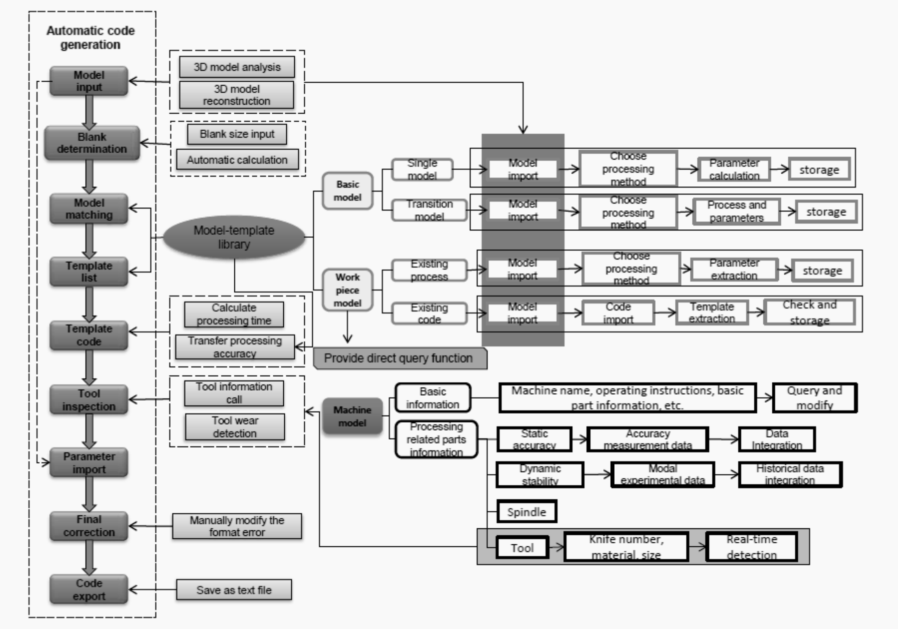
Figure 1. Functional overall framework
2.2 Functional module analysis
2.2.1 Information security.
High-grade CNC machining equipment has certain confidentiality according to its different application directions, and some application information and processing technology materials. Considering the application rights of the software and the degree to which the machine tool information can be published, the primary development of the information system needs to involve software security, that is, restricting user access rights.
2.2.2 Device related information.
The machine tool information system of this paper is based on equipment and realizes application software for all kinds of information management of processing equipment, so it is very important to store, query and update equipment information. For the system in this paper, the needs analysis of device information needs to be divided from the most basic functional attributes. For the “automatic code” to generate this main function, the design needs to be divided according to the functions and usage methods at different levels. The storage information of the machining tool is roughly divided into several aspects, as shown in Fig.2.
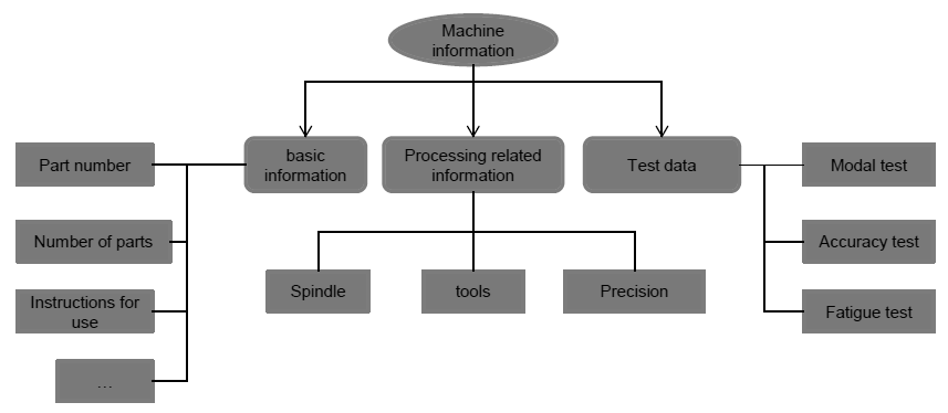
Figure 2. Device information classification block diagram
The main function of the basic data class is for the user to query and cannot be modified at will, and the auxiliary function of the automatic code generation function is not great. The processing related data is the data information that directly affects the actual machining in the machine data. It can make reasonable restrictions on the generation of the code, issue warnings for the wrong instructions beyond the machining capability of the machine and terminate the execution to ensure the rationality of the use of the equipment. The test data and analysis results of the machine tool can evaluate and test the overall level of the machine tool, forming the usage habits of the processing equipment and even predicting some key problems.
2.2.3 Processing database.
Through user input, relevant information in the form of model-code can be extracted during the user input process. After the information is stored, the query and screening will be provided according to the specific requirements of the user. So, it can build the underlying data foundation for models, processes, and usage specifications for automated code generation. This part is based on the 3D model. The demand analysis mainly focuses on the input and storage of model data and processing code. The specific content is divided into the following three categories:
(1) Simple model template
A single model is the basic unit that constitutes a complex structure. A complex component model can be decomposed into multiple simple models according to a certain method. Therefore, the processing code of a complex structural component can also be compared, filtered, and matched by the corresponding code of the decomposed base model. Connect and modify to generate. In this part, the template of the machining code base model is input, that is, only the instructions of the NC code are needed without specific parameters, but the machining method needs to be marked. It can provide the machining code template corresponding to the machine tool for the subsequent parameterized input, so that the user can get the correct machining instruction after inputting the parameters. In addition, the machining mode is also convenient for the simulation and generation of the blank shape.
(2) Transition model template
On the basis of the above basic model, the transition model is composed of 2-3 simple models, because the processing of such models is formed on the basis of the processing of its sub-models. So, it is necessary to manually arrange simple processing techniques and simulate the generation of blanks. Then the template of the processing type and the processing code is selected and the processing code template of such a transition model is formed and added to the database, as shown in FIG.3.
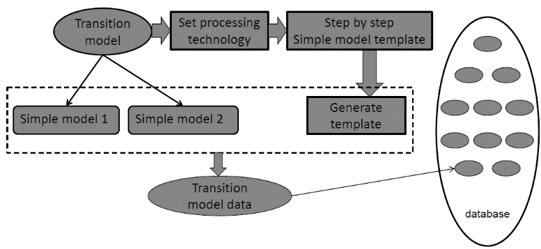
Figure 3. Transition model storage diagram
(3) Complete workpiece machining information input
There are also some 3D models of the workpiece, machining accuracy, machining process and CNC code and other information has been designed and verified by actual machining. Such data can be used not only as empirical data for equipment use, but also as a source of information for the automatic code database, which can be used as a reference for subsequent processing. It can also reflect the processing level and processing capability of processing equipment, allowing users to intuitively use software. Find out if your device can meet its needs.
The overall structure of the database can be divided into three levels according to the model template. The matching process after the user inputs the model can be searched according to the level from high to low, as shown in Fig. 4.
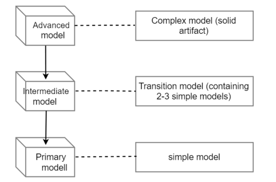
Figure 4. Model hierarchy diagram
2.2.4 Equipment tool reliability.
The stable and reliable function of each functional component of the equipment is the basic condition for the smooth processing of the numerical control equipment. The most direct component related to the actual machining is the machining tool, so the software needs to set up the corresponding part to fulfil the use of the tool, wear detection, life estimating and other requirements. The wear condition of the tool can be converted into image information by the image imposition detecting device and transmitted to the computer software, as shown in Fig. 5.
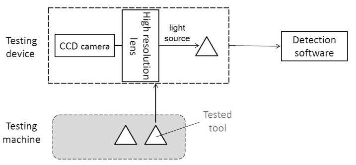
Figure 5. Tool wear detection system
The single test data can directly reflect the real-time wear and reliability of the tool, suggesting whether the user needs to change the tool in time, or directly reflect the specific situation of the tool tip. The data of multiple test records can form a tool wear experience data table. Based on this empirical rule, the remaining time of the tool can be simulated and predicted for the next time, so that the user can refer to the time factor when using the tool to realize the tool life expectancy.
2.3 Interface frame design
On the basis of functional analysis, an interface is set up for different contents, and the interface structure is proposed in combination with the operation flow of the software as shown in Fig. 6.
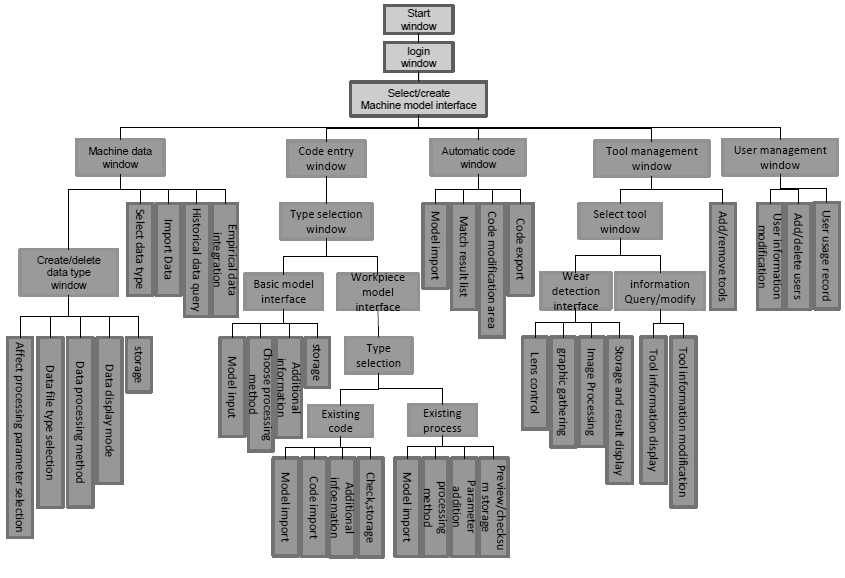
Figure6. Interface overall architecture
3. Software development overview
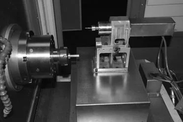
Considering that the processing equipment supporting software needs to have certain platform portability, the software is built using Java language, and the development environment adopts eclipse editor. The database uses a relatively popular small database Access to store information such as names, features, paths, etc and other files are stored in subfolders. Use jdbc mode for the connection between them and the call-component statement as follows: // Register driver Class.forName(“com.hxtt.sql.access.AccessDriver”); // Establish a link Connection conn=DriverManager.getConnection(“jdbc:Access:///data/database.accdb”,””,””); // Execute sql statement Prepared Statement ps=conn.prepareStatement(String sql); The structure of the turning and milling machine tool independently developed in this paper is based on the processing data shown in Fig. 7. The data structure of the model-processing code in the software is designed according to the numerical control instructions used in the actual machining code.

Figure 7. Machine structure physical map
4. Summary
The establishment of an information system for a specific type of machine tool helps to integrate all aspects of processing equipment into a unified information file, forming a unique knowledge base of the machine tool. The user of the equipment can input the surveyed equipment usage information and customized process information into the system to improve the composition of the knowledge base. The system can automatically generate the machining program according to the shape, size, precision and other requirements of the machined parts. This not only improves the efficiency of the equipment, but also effectively records the processing experience of the equipment itself.
In this paper, the overall scheme of automatic generation of information system for machining code proposed by turning and milling machine tool is summarized into various related functional modules, and the interface frame is established according to the functional area. We mainly completed the important work of software development in the early stage, providing clear ideas and specific reference for the specific implementation of the software. In addition, this design method can also be applied to other types of processing equipment, which is conducive to the establishment of the processing equipment Internet platform, forming an interface template for platform file transmission for wider promotion and use. This helps lay the foundation for achieving a higher level of automation of machine tool equipment.
References
[1] S Z. Y. Xv. (2015) Overall design of high precision micro-small turning and milling machine tool. 15-26.
[2] Q. Guo. (2011) Current status and development direction of CNC automatic programming technology. Value Engineering, 30(28):41-42.
[3] W. J. Liao, JW. Yu, H. Wang. (2008) Research on Automatic Programming System of CNC Lathe Based on Feature Recognition. Mechanical Science and Technology, 27(4):532-536.
[4] Joshi S, Chang T C. (1998) Graph-based Heuristics for Recognition of Machined Features from a 3D Solid Geometric Data Base. Computer-Aided Desigh, 20(2):58-66.
[5] Q. Xiong, C. Chen. (2009) Research on Information Processing Platform of CNC Machining Process Based on Knowledge Fusion. Precision manufacturing and automation, (4):55-58.
[6] X. H. Luo,Y. Liu. (2008) The overall design of knowledge-based CNC programming system. Mechanical Engineering and Automation, (6):175-176.
[7] H. G. Liu, J. J. Wang. (2018) Design and Implementation of Intelligent Manufacturing Tool Management System Database. Tool technology, (52):54-59.